
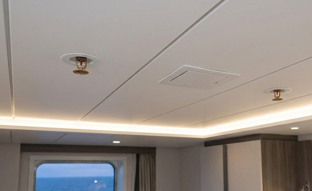
During the commissioning phase of a newbuilding, the sprinkler system is tested to verify its reliability. During commissioning, at the first attempt sometimes automation and pump start system can fail but generally with few adjustment the system is able to run properly.
Water is suctioned from the distilled water tank or freshwater tank and delivered to the main manifold by the sprinkler pump. New system have pump driven by converter, therefore less is the pressure on the manifold bigger is the fire and so pump start increasing the rpm to increase the delivered flow rate.
But sometimes, during commissioning happen a major problem.
he pump runs, suctions the water, and delivers it — but the farthest nozzles in the fire zone show too low a delivery pressure, and the flow rate is visibly lower than at the other heads.
It is a liability dressed as a safety installation. And yet, across both industrial and marine applications, this is precisely the failure mode that recurs, not because the equipment is poor, but because the engineering behind it is not properly well executed
Fire is the most consistently dangerous hazard at sea and therefore port authorities inspect the related system with big attention in order to reduce as much as possible the risks onboard.
Nevertheless, according to the Paris MoU‘s 2024 annual report, fire safety deficiencies accounted for 17.2% of all Port State Control findings , the largest category by a significant margin.
Quick Facts
- Marine sprinkler system design under SOLAS / FSS Code Chapter 8
- Minimum pressure at the highest sprinkler head: 4.8 bar
- Maximum coverage per head: 16 m² (most designs use ~12 m² in practice)
- Maximum spacing between heads: 4 m
- Maximum distance from a bulkhead/boundary: 2 m
- Fire safety deficiencies = 17.2% of all Paris MoU Port State Control findings (2024)
Statutory Baseline
SOLAS Chapter II-2 sets the principal fire safety requirements, organised around three core objectives:
- prevent fire and explosion,
- reduce risk to life,
- and reduce risk of damage to ship and cargo.
The automatic sprinkler system is one of the primary “tools” through which those objectives are met. When it is engineered incorrectly, the entire protective architecture is undermined and ship is out of compliance.
The Hydraulic Calculation Problem
Incorrect hydraulic calculations are more common than the industry tends to acknowledge, and their consequences are dangerous because they are invisible until someone doesn’t detect it during a test.
The Most Hydraulically Remote Area Principle
The core principle governing any water-based fire suppression system is that water supply must be capable of meeting the pressure and flow rate demand at the most hydraulically remote area of the system.
This is the design philosophy that determines whether the system will actually work.
Common Calculation Errors
When pipe diameters are oversized in some sections and undersized in others, flow distribution becomes unbalanced across the protected zones.
The result is that remote sprinkler heads, the ones furthest from the pump, at the end of the longest branch runs, often at the highest elevations, receive insufficient pressure and flow rate at the moment of demand.
Under FSS Code Chapter 8, as implemented through SOLAS, the pressure at the highest sprinkler head in the system must not be less than 4.8 bar, with each head capable of covering a maximum area of approximately 16 square metres (in practice, most designs use a more conservative 12 m² per head).
The hydraulic calculation is the document that should demonstrate compliance with these parameters for every head in the system under worst-case demand.
When it contains errors such as:
- incorrect pipe friction coefficients
- dimensionless resistance coefficient K
- inaccurate elevation heads,
- poorly defined design areas.
The error is locked in at design stage. It cannot be discovered by visual inspection.
Why Marine Routing Makes It Worse
Unlike a land-based installation where the designer works within a relatively predictable geometry, marine pipe routing must consider structural frames, tank tops, void spaces, many other pipelines and valves in narrow spaces and accommodation layouts across multiple decks and hull sections.
The routing complexity directly affect head losses, elevation differentials, and the pressure available at remote heads; And a calculation that works on a software may not reflect what actually gets built.
Piping Layout: Where Good Systems Go Wrong
Beyond the calculation itself, the arrangement of the piping network introduces a second layer of failure potential that deserves its own engineering attention.
Long pipe routing with excessive fittings is the most common layout error.
Suction Line Design Mistakes
Every elbow, every tee, every reducer introduces pressure loss that the hydraulic model should account for but frequently does not. When the suction pipeline is poorly designed, incorrect pipe sizing, inadequate net positive suction head available (NPSHa) for the pump, poorly positioned suction strainer, the consequences emerge at commissioning in ways that are difficult to assess.
Pumps running at excessively high RPM to compensate for a hydraulically undersized or poorly routed suction line are a reliable symptom. So is failure to prime. Both indicate that the pump is operating outside its design point.
Water Hammer Risk Factors
Pressure changes across the network follow naturally from pump incorrect working point. Response times increase and In the worst cases, water hammer becomes a concern.
Water hammer, the pressure surge generated when a moving liquid column is suddenly forced to stop or change direction, has common triggers that are all present in sprinkler systems:
- fast valve movements
- pump starts and stops,
- and sudden flow demand changes.
Air pockets in the piping intensify the effect considerably.
Persistent pressure surges cause pipe joint leaks, cracked valves, and damaged sprinkler heads. In a marine environment, where pipework runs through enclosed and often inaccessible spaces, discovering that damage after the fact is both expensive and operationally difficult to fix.
Nozzle Positioning and the Interior Design Conflict
Of all the integration problems that arise in marine sprinkler system design, the conflict between nozzle positioning requirements and interior design is the most persistent and the most “politically” charged within a project team.
SOLAS / FSS Code Spacing Requirements
The rules governing nozzle placement in marine sprinkler systems are specific and non-negotiable. Under SOLAS-derived requirements and FSS Code Chapter 8, sprinkler heads must be spaced not more than 4 metres apart and not more than 2 metres from any bulkhead or boundary forming the perimeter of the protected space, with each head required to cover approximately max. 16 square metres of floor area.
These parameters define the maximum coverage geometry within which the system can be designed.
They are derived from the thermal and hydraulic performance characteristics of the sprinkler head itself, its K-factor, its response time index, its deflector geometry, and from the fire engineering assumptions into the regulatory framework.
Where Interior Design Creates Conflicts
Interior design on cruise ships and superyachts increasingly tests these parameters.
Suspended ceiling systems with irregular cielings, decorative bulkheads that subdivide spaces below the sprinkler installation height, structural beams and architectural features that create thermal shadows; all of these affect whether a sprinkler head in a nominally compliant position will actually deliver adequate water distribution to the floor area it is supposed to protect.
- A head positioned at a geometrically correct location above a decorative beam may be thermally isolated from the fire gases that need to activate it.
- A head positioned correctly in an open plan space may fail to cover areas subdivided by later-installed furniture or millwork.
The interior designer finalises ceiling arrangements. The marine systems engineer design heads against an earlier (older) version of the ceiling drawing.
The shipyard installs what is on the approved plan.
The result is discovered during commissioning or, worse, during a flag state inspection.
On new construction projects involving complex accommodation spaces, the resolution requires early and continous coordination between marine system engineers, naval architecture, and interior design. The sprinkler nozzle layout is not a detail that can be retrofitted around interior design decisions.
On cruise vessels where a single deck may contain hundreds of individually designed cabin and public space configurations, this coordination leads to a significant engineering management challenge that must be resourced accordingly.
What Correct Engineering Looks Like
In marine systems of this nature, an incorrect pipe layout, routing, or inaccurate pressure drop and hydraulic calculations are not acceptable.
Errors of this kind can cause rework onboard during commissioning or, in the worst case, serious deficiencies while the vessel is in operation. The sprinkler system is a critical safety system and therefore demands the utmost care across all three project phases:
- Preliminary design
- Engineering
- Assembly
Correct engineering and proper sizing are not enough on their own, the system also needs the right fire protection coverage.
The preliminary design must therefore account for all areas to be covered and the maximum spacing between heads.
Equally, a well-engineered system that is not properly assembled for example, with additional unplanned elbows installed, or pipe diameters differing from those specified in the PFD can again result in a system that does not perform as intended.
For systems of this nature, having a well-informed and experienced engineering team is essential to avoid issues and keep the vessel safe. Knowledge of the assembly phase and the challenges that arise during shipbuilding is a significant advantage in preventing hidden mistakes and accelerating the overall process.
At Flowazur Consulting, we bring many years of onboard experience combined with strong engineering expertise. Within our engineering service, we support shipyards and shipowners during the design of sprinkler systems and throughout the installation phase, in order to avoid the most common issues and maintain compliance.
Book a call with one of our engineers to discuss your project.
5 Things to Verify Before Commissioning a Marine Sprinkler System
- Hydraulic calculations validated against the most hydraulically remote head.
- Pipe friction coefficients, K-factors, and elevation heads checked against as-built
routing. - Suction line sized correctly with adequate NPSHa for the installed pump
- Nozzle layout cross-checked against the latest interior design/ceiling drawings,.
- Assembly matches the approved PFD exactly, no unplanned elbows or substituted pipe
diameters
Frequently Asked Questions
Q: What is the minimum pressure required at a marine sprinkler head under FSS Code Chapter 8?
A: The pressure at the highest sprinkler head must not be less than 4.8 bar, as required by FSS Code Chapter 8 and implemented through SOLAS Chapter II-2.
Q: How far apart can marine sprinkler heads be spaced?
A: Under SOLAS-derived requirements and FSS Code Chapter 8, heads must be spaced no more than 4 metres apart and no more than 2 metres from any bulkhead or boundary, each covering approximately up to 16 m² of floor area.
Q: What causes water hammer in a marine sprinkler system?
A: Water hammer is typically triggered by fast valve movements, pump starts and stops, and sudden flow demand changes, effects that are intensified by trapped air pockets in the piping.
Q: Why do marine sprinkler systems fail during commissioning rather than earlier?
A: Hydraulic calculation and layout errors are invisible until the system is tested under real demand, a calculation that validates on software may not reflect what is actually built onboard, especially given the routing complexity of marine spaces.
Q: Who is responsible when sprinkler nozzle placement conflicts with interior design?
A: Resolving this requires early, continuous coordination between marine systems engineers, naval architecture, and interior design, the nozzle layout should not be treated as a detail retrofitted around interior design decisions.