
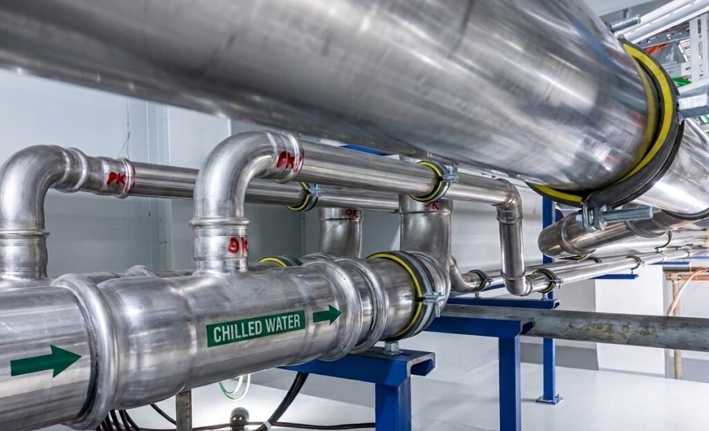
There is a particular kind of frustration that comes with commissioning a chilled water system that looks right on paper and then watching it fail to perform in service.
The chiller is running: the compressor raises the pressure on the gas circuit; the expansion valve reduces that pressure through an expansion process, and the gas drops in temperature, delivering cold to the chilled water system.
But yet, served spaces as accommodation areas, control rooms, server rooms, cargo handling spaces cannot hold their temperature setpoints.
Complaints come in from crew. The vessel operator calls the shipyard. The shipyard calls the specialized company contracted. And eventually, someone starts looking at the drawings wondering where it went wrong.
In most cases, the equipment itself is not the problem.
What went wrong happened earlier at the design stage, in the hydraulic calculations, in decisions about pump selection and pipe network layout that seemed conservative enough at the time.
This article addresses the three most common technical failure modes in marine chilled water systems, and explains why getting them right the first time is the only approach that makes economic sense.
Quick Facts - the 3 most common marine chilled water design failures
- Hydraulic imbalance: unbalanced branches trigger valve hunting, unstable control,
- and expensive re-piping after installation.
- Pump/system mismatch: over-pumping wastes energy and can trip the chiller on low
- ΔT; under-pumping means the system can’t meet peak thermal load
- Air in the system: trapped air reduces heat transfer even when every other
The hydraulic balance problem is more common than the industry admits
A chilled water system distributes cooled water from a central chiller plant through a manifold and its pipe branches that reach air handling units, fan coil units, and process cooling coils distributed across the vessel.
How Valve Hunting Develops
Each of those “users/services” units needs a specific flow rate to achieve the heat exchange the design calls for. When the hydraulic network is not properly balanced, when the pressure losses through each branch are not calculated correctly and compensated for, some branches receive more flow than they need while others receive less.
The consequences are coils receiving excess flow tend to perform acceptably but waste energy. Coils receiving insufficient flow cannot absorb the heat the space requires, regardless of how cold the chilled water supply temperature is.
The temperature differential across those coils collapses, and the space temperature climbs.
Occupants adjust thermostats. Control valves respond by opening and here the problem compounds.
When a control valve opens to compensate for insufficient flow, it increases the pressure differential across other branches in the piping system. Those branches were already receiving adequate or excess flow. Now they receive more. Their control valves begin to close.
The Cost of Fixing It After Installation
This creates a dynamic instability, what engineers call valve hunting , where control valves across the system are in constant modulation, none of them able to reach a stable operating point because the underlying hydraulic conditions are not stable. The fault is clearly the piping system design.
Correcting hydraulic imbalance after installation is expensive.
It requires either re-piping sections of the distribution network, adding balancing valves and commissioning them under operational conditions, or both.
On an operational vessel, that means planned downtime and almost certainly a claim against whoever signed off the original design.
Differential pressure control at pump level is where energy waste begins
The second systemic failure mode is misalignment between the pump curve and actual system resistance.
Marine chilled water systems are typically served by centrifugal pumps operating under variable flow conditions, with differential pressure control maintaining a target pressure differential across the system. This is achieved using pump units driven by variable-speed under inverters.
Over-Pumping: When pressure losses are underestimated
If the design system resistance curve is calculated incorrectly, which happens when pipe lengths are approximated, fittings are underestimated, or future system modifications are not accounted for, the operating pump will find itself either significantly to the left or right of its design point on the performance curve.
When Resistance Is Overestimated
Over-pumping, where the pump delivers more flow than the system requires, is the more common outcome when resistance is underestimated.
The excess flow reduces the temperature differential between supply and return, the ΔT, which reduces chiller efficiency, increases electrical consumption, and in extreme cases, triggers chiller safety trips on low ΔT conditions.
At the opposite, when system resistance is higher than designed, the pump operates in a low-flow scenario. Flow velocities drop below the design point at remote users/services, heat exchange performance decreases, and in hot ambient conditions, the system simply cannot cope with peak thermal load.
Both scenarios are preventable with accurate hydraulic calculation, modelling and proper pump selection referenced against the actual system characteristic curve, not an assumed one.
Air in the system: the hidden performance penalty
The third failure mode is less dramatic in presentation but equally damaging in effect.
During filling, draining, and refilling operations , which occur at commissioning, after maintenance, and periodically throughout a vessel’s service life , air becomes trapped in the pipelines. This is not a minor inconvenience.
Why Air Pockets Kill Heat Transfer
The heat transfer coefficient between a chilled water coil and the water flowing through it depends entirely on the water being in continuous contact with the pipe wall and coil surface.
Air pockets interrupt that contact.
They reduce the effective internal cross-sectional area available for flow and create insulating voids at the pipe surface where convective heat transfer should be occurring.
The result is a measurable reduction in thermal performance across any coil or heat exchanger affected and a corresponding increase in energy consumption as the chiller works harder to compensate for a system that is not transferring heat at its design rate.
Designing the Venting Strategy Correctly
A properly designed venting strategy places automatic air vents at every hydraulic high point in the system as well as at points of low velocity where air can become entrained and stagnant.
The venting system must also be dimensioned for commissioning scenarios where large volumes of air may be present, not only for steady-state operation where residual air is being progressively purged.
Getting this right at the design stage costs almost nothing. Retrofitting an adequate venting strategy on an operational vessel, by contrast, requires managing hot work permitys, work supervision and difficult work-operation in narrow spaces often inaccessible.
What a properly engineered chilled water system actually requires
These three issues: hydraulic system imbalance, incorrect pump-system matching, and inadequate venting; share a common root cause.
They are all the result of design decisions made quickly, with insufficient rigour, by engineers who may be competent in general mechanical systems but who have not spent enough time with the specific hydraulics of closed-loop marine chilled water circuits.
A system designed to perform correctly from the outset requires three things to be resolved properly at the engineering stage.
- The thermal load across every served space and machinery must be calculated accurately.
- The pressure losses through the entire pipe network, including all fittings, control valves, coils, and heat exchangers at their design flow rates, must be calculated before a single pipe is fabricated.
- The venting strategy must be laid out as a deliberate engineering deliverable, not added as an afterthought during the draughting stage.
When those three elements are resolved correctly, the results are clear: Energy consumption is not excessive, Control systems operate as expected, Crew spaces hold their setpoints. Maintenance intervals are not compressed by a system that is working harder than it should be.
At Flowazur Consulting we have designed chilled water systems and managed their commissioning as well. With our engineering service, we support shipyards and shipowners during the initial engineering phase to avoid the most common issues that arise only during the operational phase, which too often lead to crew and, in the worst cases, client claims.
We reduce project risk while supporting the engineering department
Book a call with one of our engineers to discuss your project.
Frequently Asked Questions
Q: What causes valve hunting in a marine chilled water system?
A: Valve hunting happens when hydraulic branches are unbalanced: a control valve opens to compensate for insufficient flow, which raises the pressure differential on other branches, causing their valves to close in response, creating constant modulation with no stable operating point.
Q: Why does a chilled water system fail to hold temperature setpoints even when the chiller is working correctly?
A: The chiller itself is rarely the problem. Insufficient flow at specific coils, caused by uncorrected pressure losses across the pipe network, collapses the temperature differential at those coils regardless of how cold the supply water is.
Q: What happens when a chilled water pump is oversized for the actual system resistance?
A: Over-pumping reduces the temperature differential (ΔT) between supply and return, which lowers chiller efficiency, increases electrical consumption, and in extreme cases can trip the chiller on a low-ΔT safety condition.
Q: Why is air in a chilled water system a performance problem, not just a minor issue?
A: Air pockets interrupt contact between water and pipe/coil surfaces, reducing the effective flow area and creating insulating voids that block convective heat transfer — measurably reducing thermal performance even when every other component is correctly sized.
Q: When should chilled water system hydraulics be checked — design stage or after installation?
A: At design stage. Correcting hydraulic imbalance after installation requires re-piping sections of the network or adding and commissioning balancing valves under operational conditions — both mean planned vessel downtime.