
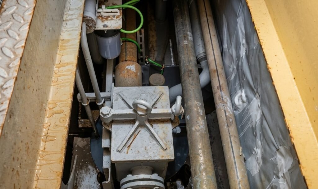
The bilge system is the second most important safety system onboard, after the fire-fighting system
It is not an auxiliary system, not a propulsion system, not a system that anyone notices during watchkeeping.
It sits behind flooring, under gratings, in double-bottom and void spaces.
And when the system is run from ECR, it draws from every bilge well to a pump that discharges the water into the (dirty) bilge holding tank.
As the bilge is a safety system, its hydraulics and piping must be designed, calculated and installed with care, during an emergency scenario there is no second chance.
SOLAS Chapter II-1, Regulation 35-1, is very clear on what the system must be capable of:
- Efficient pumping from and draining of any watertight compartment, under all practicable conditions.
- Two power pumps minimum on cargo ships, with specific redundancy requirements for passenger vessels.
- Non-return valves required wherever the piping passes within one fifth of the ship’s beam (B/5 rule) from the side.
The regulatory language is explicit and the classification society rules that implement it are detailed. None of that prevents a system from being technically compliant on its P&ID and hydraulically inadequate once installed
Quick facts — bilge system design under SOLAS Chapter II-1, Regulation 35-1
- Minimum – two power-driven pumps – required on cargo ships (more on passenger vessels)
- Non-return valves mandatory wherever piping runs within,one fifth of the ship’s beam (B/5 rule) from the side
- Theoretical maximum suction lift at sea level: ~10.3 metres
- Realistic practical suction lift for an installed arrangement: 6 to 8 metres
- Non-return valve testing interval: not exceeding six months, per P&I club guidance
Gap Between Compliance and Performance
A P&ID that satisfies class approval does not guarantee the system will work correctly once installed.
This distinction is the source of most bilge system problems encountered during and after commissioning, and it is one that deserves direct acknowledgement:
Why Class Approval Doesn’t Guarantee Hydraulic Performance
Classification surveying checks that pumps are correctly dimensioned, that the required number of pumps is installed onboard, and that the right components are specified in the right places.
It does not, and cannot, verify on the paper that the hydraulic performance of the installed arrangement will match what the design assumes.
The most sensitive points are:
Centrifugal bilge pumps are typically not self-priming, or their self-priming system is not sufficient on its own
They require liquid to be present at the pump impeller before they can develop suction. Where the pump is positioned above the bilge well it is drawing from, the suction side of the system must be primed: air must be eliminated from the suction pipeline and replaced with liquid before the pump can operate.
This is achieved through a dedicated priming pump, a vacuum priming unit, or a foot valve.
The Practical Limits of Suction Lift
The practical limitation is the physical height difference (geodetic) between the bilge well and the pump suction inlet. At sea level, the theoretical maximum suction lift for any pump drawing water is approximately 10.3 metres, representing the atmospheric pressure column available to push water up into the vacuum created at the pump inlet.
In practice, with pressure losses in the suction line, minor air leaks at flanges and gaskets, the real suction lift of an installed bilge pump arrangement is significantly lower , commonly cited in the range of 6 to 8 metres for practical installations, and lower still where the suction pipe has a significant length.
When the suction lift in the installed arrangement exceeds what the priming system can overcome, the pump will draw intermittently. The P&ID will show a compliant arrangement. The system will fail the operational test.
Debris, Mud Boxes, and What Happens When Flow Stagnates
The second category of bilge system failure is related not to hydraulics but to operational environment.
Bilge wells collect water. They also collect everything that water carries in an engine room or cargo hold environment:
- rust particles from hull plating and structural members,
- paint chips from corroding surfaces,
- residues from cleaning operations,
- sludge from machinery drainage,
- and various solid debris that finds its way into the lowest points.
A well-designed bilge well concentrates this material at the suction, where a mud box strainer intercepts it before it enters the suction pipe branch. The strainer protects the pump.
The mud box requires periodic cleaning to maintain the strainer’s flow-through capacity.
The design of the bilge well determines how effectively solid material is isolated and how frequently the mud box must be serviced.
How Stagnation Develops
Poorly designed wells create the conditions for two overlapping problems.
The first is stagnation. In a bilge well with insufficient internal circulation, because the suction inlet is positioned too high in the well, settled material accumulates and compacts.
Sludge builds up and progressively reduces the effective internal volume of the well and ultimately begins to close the suction pipe below the mudbox.
Well Accessibility and Maintainability
The second is maintainability. Bilge wells require periodic access to remove the major debris and sludge that accumulate at the bottom. A well that is too narrow, poorly shaped, or difficult to reach will not be cleaned as thoroughly, or as often, as the maintenance schedule requires — and the accumulation problem described above simply returns faster.
As with the non-return valve accessibility discussed later in this article, well accessibility is a specification decision that must be resolved at design stage, not a maintenance afterthought.
Non-Return Valves: The Component That Cannot Be Allowed to Fail Open
The bilge system’s non-return valves perform two distinct functions, and the failure of either creates serious operational consequences.
Their primary function is to prevent backflow from the bilge manifold into the compartment being served. SOLAS Regulation 35-1 requires non-return valves specifically where bilge piping runs within one fifth of the ship’s beam (B/5 rule), to prevent a damaged pipe in a flooded compartment from introducing water into the bilge manifold.
In cargo hold bilge systems, screw-down non-return valves at each bilge suction point prevent water pumped into one hold from reaching another through manifold
The failure mode that is most operationally dangerous is the valve remaining stuck in the open position.
Non-return valves rely on a simple mechanism: a disc, flap, or plunger that lifts under forward flow pressure and seats under gravity or spring pressure when flow stops. In a bilge well environment, where the media contains sediment, rust particles, paint debris, and biological material , the seating surface of the valve is continuously exposed to contamination that can mechanically prevent the closure element from seating cleanly.
A disc that lifts cleanly under suction but then catches a rust particle on its seat cannot close fully when suction stops. The valve remains in the partially or fully open position.
When this scenario happens on a bilge well that is empty or nearly so, the consequences are immediate and specific:
- the open valve connects the suction line to the atmosphere of the bilge well.
- Air enters the suction pipe.
- The partial vacuum that the pump has established across the system is broken.
- The bilge pump loses prime.
- It will continue to run drawing air through the failed valve and discharging nothing.
The Maintenance Importance
Operational issues such as those described above can be prevented with good, well-scheduled onboard maintenance
In a flooding scenario, the bilge system failure is not an operational inconvenience. It is a direct threat to the vessel’s damage control capability.
The maintenance requirement for non-return valves in bilge systems is consequently much more demanding than the simplicity of the valve design might suggest.
Regular testing, typically at intervals not exceeding six months, as advised in P&I club guidance and the Nautical Institute’s reference texts, is required to confirm that each valve both opens under suction and closes reliably when suction is removed.
Valves that cannot be tested in service, because the design has positioned them in locations without adequate access, will not be tested. The maintenance schedule will record the test as completed on the basis of what was reachable, and the inaccessible valve will remain in an unknown condition.
This is, again, a design problem. Valve accessibility is not a field issue. It is a specification that must be addressed before the system arrangement is finalised.
What the System Actually Requires
The bilge system engineering requirements that determine long-term reliability are not complex in concept. They are demanding in application, because they require the designer to have an in-depth understanding of the system’s entire operating envelope — not just its nominal conditions.
Hydraulic performance calculations must be based on the actual installed suction height for each bilge well, accounting for:
- pipe losses
- fitting resistances
- and the realistic capability of the priming system
Any well where the calculated required suction lift approaches or exceeds the priming system’s confirmed capability represents a risk that must be resolved at the design stage either by repositioning the pump, resizing the priming system, or redesigning the suction routing.
Bilge well geometry and strainer arrangement should be assessed for sediment management and maintenance access before these elements are installed onboard.
Vibration assessment should be performed for all sections of bilge piping connected to reciprocating pumps, identifying resonance risks and dynamic stress concentrations.
For these reasons, only qualified and experienced marine systems engineers with extensive onboard experience can effectively limit project risk and avoid the most common design errors.
At Flowazur Consulting, through our engineering service, we support shipyards and shipowners in designing bilge systems that avoid the most common errors during the engineering phase.
Book a call with one of our engineers to discuss your project in detail.
Frequently Asked Questions
Q: What is the maximum theoretical suction lift for a bilge pump?
A: At sea level, the theoretical maximum suction lift for any pump drawing water is approximately 10.3 metres, the atmospheric pressure column available to push water into the vacuum at the pump inlet. In practice, with pipe losses and minor air leaks, realistic suction lift for an installed bilge arrangement is commonly 6 to 8 metres.
Q: Why can a bilge system be technically SOLAS-compliant and still fail in practice?
A: Classification surveying confirms that the correct number and type of pumps and components are installed as specified. It does not verify that the hydraulic performance of the installed arrangement, suction lift, pipe losses, priming capability, will match what the design assumed.
Q: What happens when a bilge non-return valve gets stuck open?
A: If the valve fails to seat due to sediment or debris, it connects the suction line to the atmosphere of the bilge well once suction stops. Air enters the pipeline, the pump loses prime, and it continues running while discharging nothing, with no working bilge capacity in that well.
Q: How often should bilge non-return valves be tested?
A: At intervals not exceeding six months, per P&I club guidance and Nautical Institute reference texts, to confirm each valve both opens under suction and closes reliably when suction is removed.
Q: Why do bilge wells need mud box strainers?
A: Bilge wells collect rust particles, paint chips, sludge and debris along with the water. A mud box strainer intercepts this material before it reaches the suction pipe, protecting the pump, but it requires periodic cleaning, and a poorly designed well increases how often that cleaning is needed.