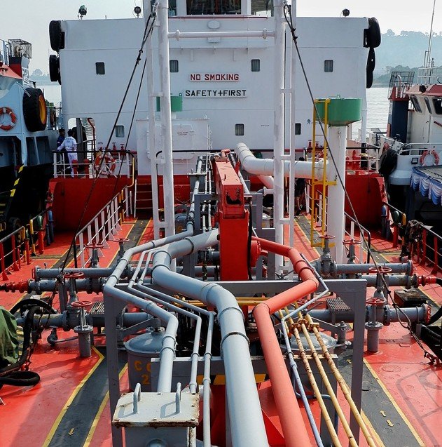
APPLICATION FIELD
IACS UR P2, “Rules for piping design, construction and testing,” governs piping made of carbon, carbon-manganese, alloy steels or non-ferrous material normally fitted on board.
It set a defined list of services:
- air
- vapour
- gas
- other than cargo/process gas
- water
- lubricating oil
- fuel oil
- hydraulic fluid systems for steering gear
- toxic gases and liquids
- cargo oil
- tank cleaning piping
- and open-ended lines such as drains, overflows, vents and boiler escape pipes.
Pipes that form an integral part of a boiler fall outside it, and hydraulic systems other than steering gear are left to each Classification Society’s own consideration rather than covered by a fixed rule. Piping for liquefied gas cargo and process service is routed instead to UR G3 and W1. P2 carries the same three scope exclusions as its sibling P1: chemical cargo/process piping under the IBC Code, gas cargo/fuel and process piping under the IGC and IGF Codes, and piping for other low-flashpoint fuels as defined in SOLAS II-1/2.29.
PIPE CLASS / SYSTEM TYPE
This is the UR that actually does the classifying. P2.2 is where the Class I / II / III system lives: pipes are sorted by the combination of design pressure and design temperature, together with whether the medium is toxic, corrosive, or flammable with a low flash point. That classification then drives everything downstream in P2, which welding procedures apply, how much non-destructive testing is required, which connection types are permitted at which diameter, and how rigorously a joint has to be tested before it can go into service.
Where P1 tells you how thick a pipe wall needs to be regardless of class, P2 tells you what has to happen to that pipe on the way to being installed, and that answer changes depending on which of the three classes it falls into.
RELATED RULES
- Direct sibling: UR P1 supplies the wall-thickness and general strength baseline that P2 assumes already exists; P2 then classifies the pipe and governs its materials, fabrication, welding and testing.
- Direct sibling: UR G3 and UR W1 take over for liquefied gas cargo and process piping, which P2 explicitly hands off rather than covers itself.
- Carve-out reference: The IBC Code, IGC Code, IGF Code and SOLAS II-1/2.29 define the same three excluded piping categories found in P1 — chemical cargo/process piping, gas cargo/fuel/process piping, and other low-flashpoint fuel piping.
- Cross-reference: UR F42, together with ISO 15540 and ISO 15541, sets the fire-resistance testing standard that non-metallic flexible hose assemblies must meet under P2.12 when used in flammable-media or seawater services where failure could cause flooding.
- Cross-reference: UI SC249 and MSC.1/Circ.1426/Rev.1, alongside SOLAS II-1/3-5.2, back up P2.7.2’s prohibition on asbestos-containing flange gasket material.
- Statutory backdrop: MSC/Circ.734 underpins the restriction on slip-on joints in cargo holds, tanks and other spaces that aren’t easily accessible.
RESTRICTION
Class II pipes are never permitted for toxic media, full stop; there’s no safeguard that brings them back into scope the way there is for flammable media.
Butt-welded joints without special provision for root-side quality are confined to Class II and III piping;
Class I always needs the higher-quality root treatment regardless of diameter.
Slip-on sleeve and socket welded joints are similarly boxed in, usable in Class III, but in Class I and II only up to 88.9 mm outside diameter, and never for toxic media or services prone to fatigue, erosion or crevice corrosion. Threaded connections carry their own diameter ceilings by class, tightest for Class I. Mechanical joints face the most consequential restriction of all: where their failure could cause fire or flooding, they’re excluded outright from piping sections connected directly to the ship’s side below the bulkhead deck of passenger ships or the freeboard deck of cargo ships, and from tanks holding flammable fluids.
Slip-on joints inside cargo holds, tanks and other spaces that aren’t easily accessible are likewise excluded except where the joint sits in a tank holding the same medium it’s designed for.
DESCRIPTION
P2 exists because P1’s wall-thickness calculation only answers part of the question: a pipe that’s thick enough to hold pressure still needs to be made of the right material, welded and heat-treated correctly for its service, checked by the right non-destructive method, connected using a joint suited to its class, and proven by testing before it’s trusted with people’s safety at sea.
The rule builds this out in a logical sequence. Materials come first: carbon and alloy steels are limited by temperature unless the manufacturer can demonstrate long-term creep and rupture behavior at higher temperatures, copper alloys carry their own temperature ceilings, and cast iron, ordinary or nodular, is boxed into narrow, carefully specified uses because its brittleness makes it unsuitable wherever shock loading or high temperature service is likely.
Welding and heat treatment scale with class and thickness. A Class I steam line operating at high temperature and pressure has a failure consequence that a Class III drain line doesn’t, so the fabrication rigor (preheating, stress relieving, post-weld heat treatment) is calibrated accordingly.
Non-destructive testing follows the same logic, moving from full radiographic examination on larger Class I butt welds down to random sampling on Class III.
Because the design and configuration of mechanical joints vary so widely across manufacturers, P2 doesn’t attempt to prescribe a calculation method for their theoretical strength; instead, it leans entirely on empirical Type Approval testing: leakage, vacuum, vibration fatigue, fire endurance, burst pressure at four times design pressure, pressure pulsation, and pull-out testing, applied according to the service the joint is intended for.
IMPORTANT NOTE
- Sizing a pipe correctly under P1 doesn’t establish which welding, NDT or connection regime applies; that depends entirely on the Class I/II/III assignment under P2.2, and skipping that step is a documentation mistake that class engineers catch quickly.
- Fitting a mechanical joint below the bulkhead or freeboard deck on piping whose failure could cause flooding or fire is excluded outright, not a case for special consideration — finding one there during survey typically means removal and rework of the pipeline
- Slip-on joints installed inside cargo holds or tanks that aren’t easily accessible are a recurring non-conformity in as-built piping arrangements.
Frequently Asked Questions
Q: What does IACS UR P2 govern?
A: It classifies piping into Class I, II, or III based on design pressure, design temperature, and whether the medium is toxic, corrosive, or flammable, then sets the materials, welding, NDT, and testing requirements that follow from that class.
Q: How is P2 different from P1?
A: P1 sets the minimum wall thickness a pipe needs regardless of class; P2 governs materials, fabrication, welding, joint type, and testing – once that pipe is classified.
Q: Are Class II pipes allowed for toxic media?
A: No. Class II pipes are never permitted for toxic media, with no exception that brings them back into scope.
Q: What’s the diameter limit for slip-on sleeve and socket welded joints in Class I and II piping?
A: 88.9 mm outside diameter; above that, or for toxic media and services prone to fatigue, erosion, or crevice corrosion, they’re not permitted.
Q: Can mechanical joints be used below the bulkhead or freeboard deck on piping that could cause flooding or fire if it fails?
A: No. They’re excluded outright in that location, with no case-by-case exception.
“Flowazur is not affiliated with, endorsed by, or sponsored by ISO, ASTM, ASME or API. All standard names and numbers are property of their respective organizations.”
Expert Marine and Piping Engineers at Your Side
Piping systems often go unnoticed until they cause major problems and major rework follows. Avoid uncertainty, reduce project risk, and keep your schedule on track with Flowazur Consulting.
Our team includes highly experienced, specialized:
- Piping Consultors
- Marine system engineers
- Piping System Engineer
- Technical Managers