
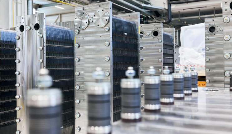
Photo: Industry chemistry
The maritime industry’s transition toward low and zero-emission propulsion has brought fuel cell technology from research programmes and pilot projects into active consideration for commercial vessel newbuilds and retrofits.
Classification societies have published dedicated guidelines and Flag state administrations are developing approval frameworks.
Shipowners are issuing tenders that include fuel cell-based power systems as a specified option. The technology itself is mature enough. What remains difficult is integration.
Replacing a diesel generator with a fuel cell system is a systems engineering challenge of a different order. A diesel genset requires fuel supply, cooling, exhaust, and electrical connection.
A fuel cell installation requires all of that, plus dedicated process air management, electrochemical water handling, precisely controlled thermal circuits with specific conductivity requirements, compartment ventilation that is totally separate from the electrochemical process, and safety architectures different to conventional marine power plant design.
Every one of those subsystems must be engineered correctly, and they must work together. A weakness point of one of these can potentially compromise the entire system.
Quick Facts
– PEM cooling circuits require deionised water below 1 µS/cm conductivity.
– Insufficient cathode air supply causes cell reversal, which permanently and irreversibly damages the stack.
– The process air system is entirely separate from compartment ventilation.
– Subsystems as cooling, ventilation, drainage, and process air are all interdependent.
The thermal management problem is more important than it first appears
Heat dissipation is a fundamental constraint in fuel cell system design.
PEM fuel cells, the variant most commonly under consideration for marine applications, operate at relatively low temperatures, typically in the range of 60 to 80 degrees Celsius for conventional low-temperature PEM, which means the temperature differential available for heat dissipation to seawater is narrower than in a diesel engine installation (narrow DELTA T).
That constraint drives the design of the cooling system in ways that are not immediately obvious to engineers approaching fuel cell integration from a conventional marine engineering background.
The cooling circuit in a PEM fuel cell installation is not a standard seawater+cooling water (LT) cooling loop.
It must use deionised water (water with electrical conductivity controlled to very low levels, typically below 1 µS/cm) because the coolant passes through electrically active components within the fuel cell stack.
Deionized water is filtered through chemical resins to remove mineral ions, but it does not reliably remove bacteria or organic compounds
RE-AGENT Chemical Suppliers
Contamination of the deionised water circuit, whether through contact with standard pipeline materials that leave ions, through cross-contamination with other onboard water systems, or simply through degradation over time, will increase conductivity, create eddy-current (Foucault) leakage paths through the coolant, and degrade both performance and safety.
Maintaining that circuit requires specific materials selection throughout, dedicated monitoring, and a clear maintenance strategy from day one of the design process.
The interface between the fuel cell’s internal deionised water circuit and the seawater cooling system is managed through a heat exchanger arrangement, typically a plate heat exchanger or a sub-cooling circuit, that transfers heat to seawater without allowing any direct contact between the two streams.
The sizing of that heat exchanger, and the control strategy that manages cooling water flow under varying electrical load conditions, must account for the full range of operating scenarios the vessel will encounter:
- partial load,
- full load,
- manoeuvring,
- port operations in high ambient sea temperatures
Process air is where the most serious failure mode lives
The cathode side of a PEM fuel cell requires a continuous, controlled supply of air, or in some high-performance installations, oxygen, to sustain the electrochemical reaction.
This is not simply a matter of ensuring the compartment has adequate ventilation.
The process air system is a dedicated subsystem with its own compressors or blowers, filtration, humidity control, flow measurement, and control logic.
It is entirely separate from the compartment ventilation system, which serves a different function entirely.
The air flow rate must be matched to the fuel cell’s working point and conditions with precision, because the consequences of insufficient cathode air supply are severe.
When oxygen availability at the cathode drops below the stoichiometric requirement, even briefly, even locally within the stack, the electrochemical reaction cannot sustain the current: as a result, fuel-cell voltage decreases, potentially to the point of collapse.
If the stack is still connected to a load, current begins to flow in reverse through the affected cells.
This reverse current condition, which the industry refers to as cell reversal or reverse power, causes electrochemical oxidation of the carbon support structures within the cathode electrode. That damage is cumulative and irreversible.
A stack that has experienced repeated or prolonged cell reversal events will exhibit permanent performance degradation and, in serious cases, will require premature replacement of stack components.
Preventing cell reversal requires:
- accurate flow rate calculations across the full load range,
- a control system that responds rapidly to load demand,
- and a process air system with sufficient response speed that cathode starvation does not occur during a change in electrical demand.
These requirements have direct implications for blower or compressor selection, for the control architecture, and for how the fuel cell system interfaces with the vessel’s power management system. They need to be resolved at the design stage, not discovered during commissioning.
Ventilation, drainage, and the subsystems that are often underspecified
The compartment housing the fuel cell system requires a dedicated ventilation arrangement that is dimensioned and controlled independently of the process air supply.
Its function is to maintain safe atmospheric conditions in the space, managing hydrogen concentration in the event of a leak, controlling temperature, and ensuring that any accumulation of hazardous gas is detected and diluted before it reaches a dangerous level.
Classification society guidelines, including DNV’s Rules for Classification of Ships, Pt.6 Ch.2 Sec.3 (Fuel Cell Installations), and the IMO’s interim guidelines for fuel cell vessels (MSC.1/Circ.1647), set requirements for ventilation rates, gas detection, and emergency shutdown integration that must be reflected in the system design from the earliest engineering stages.
Hazardous zone classification for the fuel cell compartment affects the specification of every electrical component installed within it:
- lighting,
- instrumentation,
- cable penetrations
and revisiting those decisions late in a project is both expensive and time-consuming.
Drainage is another subsystem that receives less attention than it deserves at the concept design stage.
PEM fuel cells produce water as a byproduct of the electrochemical reaction at the cathode.
They also generate condensate on the anode side as hydrogen recirculation systems cool the gas stream. Both streams need to be collected and managed.
The drainage system must handle variable flow rates and comply with applicable discharge regulations.
What successful integration actually requires
The common thread running through all of these challenges is that they are interdependent.
As with alternative fuels, the design philosophy is holistic. It means that we cannot assess any system in isolation but must instead maintain a broader view.
- The process air system dimensioning affects the thermal load on the cooling circuit.
- The cooling system layout affects compartment temperature, which in turn affects ventilation requirements.
- The drainage system layout is constrained by the structural arrangement, which is itself influenced by where the fuel cell stack is located.
None of these systems can be designed in isolation, and none of the critical calculations — thermal, hydraulic, stoichiometric, safety — can be deferred to a later project phase without creating downstream problems that cost significantly more to resolve than they would have cost to prevent.
Space and installation assessment is not a secondary consideration. Fuel cell systems, including their compressors, heat exchangers, water management systems, and power conditioning equipment, occupy considerably more volume than an equivalent diesel installation.
Early-stage space allocation, access planning for maintenance, and coordination between mechanical, electrical, and structural disciplines are not project management formalities.
At Flowazur Consulting we have experienced integration engineers who perform piping layout assessments and hydraulic, aeraulic, and pressure drop calculations to correctly integrate fuel cells onboard in our new technologies integration service.
Speeding up the engineering process while reducing overall project risk and future issues once the vessel enters operation.
Book a call with one of our engineers to discuss your project in detail.
Frequently Asked Questions
Q: Why can’t a PEM fuel cell use standard seawater cooling?
A: The coolant contacts electrically active components inside the stack, so it must be deionised water with conductivity below roughly 1 µS/cm.
Q: What happens if cathode air supply drops too low?
A: The reaction can’t sustain current, current starts flowing in reverse through the affected cells (cell reversal).
Q: Is compartment ventilation the same as the fuel cell’s process air system?
A: No.They’re entirely separate systems. Compartment ventilation manages atmospheric safety; process air feeds the electrochemical reaction itself.
Q: What byproducts does a PEM fuel cell’s drainage system need to handle?
A: Water produced at the cathode, plus condensate from hydrogen recirculation cooling on the anode side.
Q: Which guidelines apply to fuel cell compartment ventilation and safety?
A: The IMO’s interim guidelines for fuel cell vessels (MSC.1/Circ.1647), together with the relevant classification society’s own rules.