
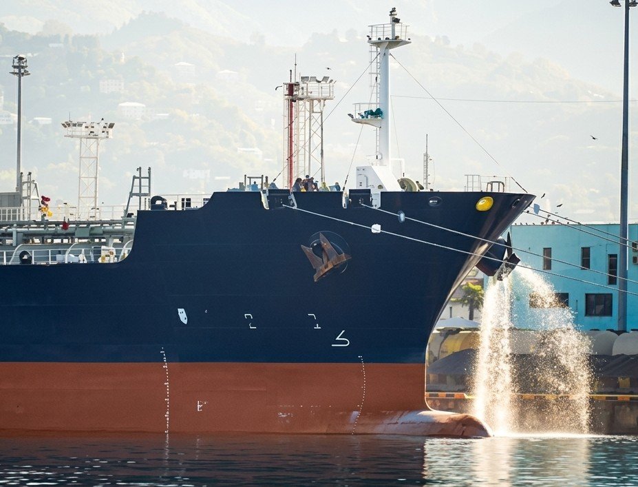
The International Convention for the Control and Management of Ships’ Ballast Water and Sediments has been in force since September 2017.
Since September 2024, every vessel in international trade is required to meet the D-2 biological discharge standard, meaning that treated ballast water must contain fewer than ten organisms per cubic metre above 50 microns in minimum dimension.
The phased implementation schedule that ran from 2017 to 2024 drove one of the largest retrofit programmes in the recent history of commercial shipping, with some installations costing individual ship operators upward of 3 million US dollars per vessel.
That investment has not always delivered the operational performance it should have.
Across different ships, a recognisable pattern arose: ballast water treatment systems that pass their factory acceptance test and complete commissioning without incident and then begin generating operational failures within the first six to twelve months of real-world service.
- UV alarms.
- Frequent filter clogging.
- Accelerated pump wear.
- In electrochlorination systems, total residual oxidant levels not in compliance.
The owner calls it a warranty problem. The engineer who looks at the actual installation usually finds that the treatment unit itself is functioning as designed. The failure is in the piping and integration engineering that surrounds it.
Quick facts — Ballast water treatment system integration
- D-2 standard: fewer than 10 organisms per m³ above 50 microns, mandatory for all vessels in international trade since 8 Sept. 2024
- BWM Convention in force since 8 September 2017
- Retrofit cost: reported up to $3 million per vessel
- CFD research on a real installation found upstream pipe bends and tee proximity to the UV reactor inlet can cause up to 8.5% flow distribution error between parallel reactors
The Treatment Unit Is Not the Problem
A type-approved ballast water treatment system is certified against its own hydraulic and biological specification. That specification defines the flow rate at which the system is designed to work, the UV or chemical dosing concentration it is designed to deliver, the filter differential pressure at which it is designed to operate, and the upstream water quality conditions it is designed to tolerate.
What the type approval does not address is how the system work when installed in a specific vessel’s existing piping arrangement, under the variable hydraulic conditions that actual ballasting operations produce.
The gap between the type-approved specification and the installed reality is where operational issues live.
Upstream Piping & UV Reactor Hydraulics
The UV reactor in a ballast water treatment system sterilises water through a radiation dose, the product of UV intensity and the time each volume of water spends within the treatment zone.
How UV Dose Actually Works
Both variables are functions of hydraulic behaviour inside the reactor.
- Intensity depends on lamp condition and water UV transmittance.
- Residence time depends on flow rate and flow distribution.
If the flow through the reactor is irregular, concentrated toward one region of the lamp while another region sees reduced flow, parts of the water are not properly treated.
The system may satisfy its nominal flow rate requirement while delivering insufficient dose to a fraction of the water. The result is a treated water not in compliance with D-2 requirements.
What CFD Studies Show About Pipe Geometry
The hydraulic conditions upstream of the UV reactor determine whether that flow distribution is uniform or not.
Computational fluid-dynamics (CFD) studies have clearly shown how the upstream piping arrangement to the BWTS can compromise its performance and render the treated water non-compliant
- The number and orientation of bends
- the proximity of tees and reducers to the reactor inlet
- the presence of flow disturbances that have not fully resolved within the required straight pipe run
This directly shifts the UV dose distribution within the reactor toward lower values, increasing the proportion of water that receives inadequate treatment.
Air Pockets in the system
Air pockets in the pipe upstream of the UV reactor can be the cause of a UV dosing not working properly.
The issue is not the ballast water treatment system but the pipiping. Air entrainment in a ballast system piping arrangement is a consequence of poor pipe routing geometry:
- high points in the pipe layout where gas accumulates,
- inadequate priming arrangements that allow air to remain in the system at startup,
- or suction pipe configurations that draw air under certain tank level conditions.
IIn a UV reactor, an air pocket passing through the treatment zone also causes a sudden change
Filters, Flow Rates, and the Clogging Problem
The filter stage in a ballast water treatment system is the first line of protection for the system: it removes larger organisms and suspended solids before the water reaches the UV reactor or electrochlorinator, protecting the downstream treatment components and improving the quality of the water entering the treatment zone.
Filter Sizing vs. Pump Capacity
Filter undersizing in relation to the ballast pump capacity is among the most frequent integration errors. The filter manufacturer specifies a rated flow range based on the filtration element surface area, the design differential pressure, and the solids loading assumptions of the type approval test conditions.
When the installed ballast pump delivers flows that exceed the filter’s rated capacity during heavy ballasting operations, the differential pressure across the filter element increases.
As a result, automatic filters detect excessive differential pressure, and the automation triggers repeated backwash cycles, making working pressure unstable.
And then alarms are triggered.
The Bypass Trap
The crew bypasses the filter to keep operations running, in breach of the
discharge compliance requirements, under the BWM Convention.
The root of this failure is a design error that occurred when integrating the BWTS with the existing piping system
Pumps Operating Away From Their Best Efficiency Point
The ballast pumps on a retrofitted vessel were originally selected and installed for a system that did not include the pressure losses introduced by a ballast water treatment system. Adding a filter, a UV reactor or electrochlorinator, pipes, valves, and instrumentation to the piping system introduces new head losses that shift the operating point on the pump curve.
What Happens Left of BEP
On a centrifugal pump, which is what most ballast pumps are, the operating point is determined by where the system resistance curve intersects the pump H-Q curve.
Adding pressure drop steepens the system resistance curve, shifting the operating point to the left of the Best Efficiency Point on the pump curve.
Operating a centrifugal pump away from its Best Efficiency Point is not a neutral condition. At flows to the left of BEP, which is what increased system resistance typically produces, internal recirculation develops at the pump impeller inlet and discharge.
This creates localised high-velocity parts that generate cavitation, eroding the impeller and casing progressively. Radial thrust on the shaft increases, accelerating bearing wear. Mechanical seal faces run under thermal and mechanical stress that shortens their service life substantially.
What Well-Executed Integration Engineering Looks Like
On a retrofit project, Ballast Water treatment unit is installed in an existing ballast system.
In this kind of project, the integration engineer’s job is to determine the flow rate and operating point of the existing pump, then select the other elements, filters, fittings, accordingly.
The integration engineer will then assess different operating scenarios to identify the resulting flow rate and operating point (considering both pump and piping system), comparing them against the BWTS requirements.
Excessive pipe head loss, an undersized priming system, or inadequate filter and fitting selection can easily lead to problems once the system is in operation..
In systems like this, where problems don’t always appear during commissioning, rework onboard is often required, adding stress for the crew and significant repair costs charged to the shipowner.
At Flowazur Consulting, with our engineering service, we design marine systems drawing on decades of marine operations experience. Therefore our expertise allow us to prevent undesired problems and so reducing the project risk.
Book a call with one of ours engineer to discuss in detail your project.
Frequently Asked Questions
Q: Why does a ballast water treatment system pass commissioning but fail months later?
A: Type approval certifies the treatment unit against its own hydraulic and biological specification , not how it behaves once installed in a specific vessel’s piping arrangement, under real ballasting conditions. Most failures originate in that gap, not in the treatment unit itself.
Q: How does upstream piping affect UV reactor performance?
A: CFD studies on real installations show that the number and orientation of bends, and the proximity of tees and reducers to the UV reactor inlet, can distort flow distribution inside the reactor, reducing UV dose in parts of the water even when the system meets its nominal flow rate.
Q: Why do filters clog and trigger bypass in ballast water treatment systems?
A: Filter undersizing relative to the actual ballast pump capacity is a common integration error. When pump flow exceeds the filter’s rated capacity, differential pressure rises, triggering repeated backwash cycles, and crews may bypass the filter to keep operations running, which breaches BWM Convention discharge requirements.
Q: What happens when a ballast pump operates away from its Best Efficiency Point?
A: Adding a BWTS introduces new pressure losses that shift the pump’s operating point, typically to the left of its Best Efficiency Point. This causes internal recirculation and cavitation, eroding the impeller and casing and accelerating bearing and seal wear.
Q: What is the D-2 ballast water discharge standard?
A: The D-2 standard requires treated ballast water to contain fewer than 10 viable organisms per cubic metre above 50 microns in minimum dimension, mandatory for all vessels in international trade since 8 September 2024.