
Engineering a methanol fuel system and its related auxiliary systems during a retrofit project on an existing merchant vessel looks straightforward when we’re working with 3D drawings, PFDs, and a project schedule. In reality, though, things look very different once we reach the assembly phase.
When those theoretical designs meet the reality of an older hull and structure during a conversion, the gap between desktop engineering and shipyard reality can widen fast.
For methanol-fuelled vessels, the air vent system is a critical safety barrier.
Methanol vapour is toxic, flammable, and roughly 10% heavier than air by vapour density though, unlike a dense hydrocarbon vapour such as gasoline, it doesn’t joint and disperse in low-lying areas in the same way;
it disperses more easily with ventilation and natural convection.
That said, in a confined, low-ventilation trunk or void, we still treat it as heavier-than-air for design purposes. Vent lines can’t be treated like a standard air vent pipe for HFO or MGO tanks.
Every spool of the vent system has to guarantee proper gas flow and total containment. For methanol, the containment arrangement must, in most cases, be double-barrier, double-walled pipes are required.
It’s worth remembering that under the IMO Interim Guidelines, a properly built double-wall fuel pipe isn’t itself considered a potential source of release; that’s precisely why a defect hidden inside the inner pipe, invisible from the outside, is so dangerous;
This case study reviews a dual-fuel conversion project where, during the design phase, we developed an air vent routing layout that turned out not to be aligned with the as-built drawings; we had been working from outdated 3D files. The result was an air vent pipe compliant at every point except one, where the assembly created a condensate pocket.
Quick Facts
- In a methanol vent system sags can trap condensed methanol vapour, risking tank over-pressure, vacuum collapse, or a hazardous liquid pocket near accommodation spaces.
- The issue was identified during a pre-delivery inspection ahead of the pressure test, and two corrective options were put forward.
- The shipyard chose to modify the ship’s structure rather than add a drainage line, to preserve the original vent routing and protect the nitrogen blanketing system.
- The fix added 7 days to the project: 2 for engineering review, 3 for procurement and structural work, and 2 for pipe re-fabrication and installation.
Retrofitting a 47,000 DWT Product Tanker
The project involved retrofitting a conventional product tanker to operate on a dual-fuel methanol system. A core part of the conversion was the design and installation of a new air vent system for the tanks converted to methanol fuel, along with a new vapour return line to the bunker station.
We began developing the new air vent system using the 3D files provided by the shipyard and the shipowner. The result was an air vent system in DN150 stainless steel (316L) piping, routed from the forward fuel tanks, running through a deck trunk, rising vertically along the aft superstructure, and terminating at a dedicated vent mast fitted with flame arrestors and P/V valves.
We had applied a standard minimum inclination of 30 degrees back toward the fuel tanks in every zone that required it, giving us a clear, continuous, self-draining pipeline capable of returning condensate to the tank.
Air vent system for Methanol and working principle
Before going into what actually happened on this project, it’s worth recalling how an air vent system on a methanol-fuelled ship behaves. As mentioned, this isn’t an atmospheric system: it’s a closed, low-pressure system.
Here’s how it works across the different ship operations:
1. Bunkering Operation
During bunkering, methanol is transferred from the barge, truck, or other bunkering source into the storage tank. As the liquid level rises, the vapour space inside the tank reduces, pushing vapour back through the vapour return line. The existing gas volume, mostly nitrogen and methanol vapour, is displaced and compressed.
To prevent overpressure, we route the displaced gas through the tank vent system. When tank pressure reaches the P/V valve’s set point, the valve opens and releases the gas mixture through the vent mast.
We size the vent system for the maximum bunkering rate and the corresponding vapour displacement rate. Its main job during bunkering is to keep tank pressure within the allowable design limits while safely discharging the displaced vapour volume.
2. Normal Fuel Consumption
During normal vessel operation, methanol is continuously supplied from the fuel tank to the fuel preparation room (FTR) and the engine supply system. As fuel is consumed, the liquid level drops and the vapour space expands.
To prevent vacuum formation, we keep the tank under nitrogen blanketing. The nitrogen supply system automatically introduces nitrogen into the vapour space to compensate for the volume of methanol removed from the tank.
Under normal operating conditions, the vent system stays inactive and the P/V valve remains closed. Tank pressure is controlled by the nitrogen blanketing system, which maintains a slight positive pressure and keeps air from entering.
The vent system is a safety device here, it doesn’t normally take part in routine tank breathing during fuel consumption.
3. Fuel Transfer Operation
During internal fuel transfer, methanol is pumped from a storage tank to a service or daily tank.
In the storage tank, the liquid level drops and the vapour space grows. The nitrogen blanketing system compensates for this by supplying nitrogen to maintain tank pressure and prevent a vacuum.
In the receiving tank, the liquid level rises and the vapour space reduces. The gas in that vapour space has to be displaced to avoid overpressure.
Depending on the vessel’s design, we either discharge that displaced gas through the vent system via the P/V valve, or return it to another tank through a dedicated vapour return line.
The Hidden Sag and the "Drain Trap" Risk
Once we lay out the basic working principles of a methanol air vent system, it becomes clear that these pipes carry both nitrogen and methanol vapour. That has to push designers to assess, both at the design stage and during assembly, the risk of methanol vapour, or liquid pockets, forming inside the vent piping.
Back to the case study:
the problem surfaced during the assembly phase at the shipyard.
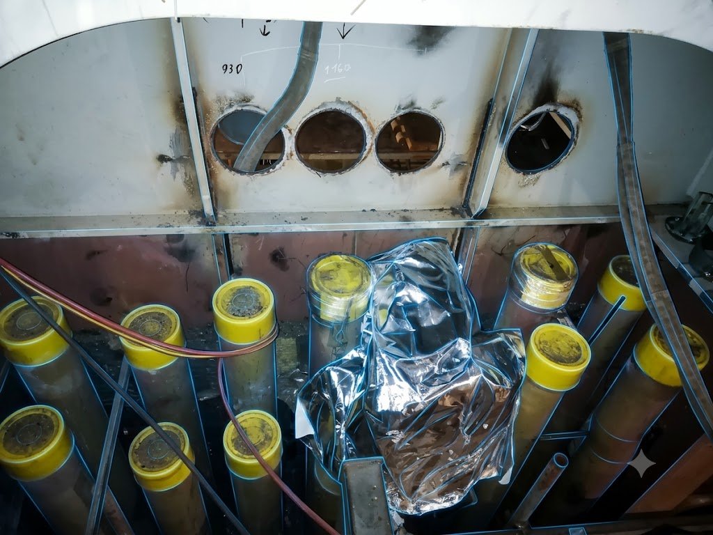
When the outfitting team started installing the DN150 pipe spools through the trunk, they ran into a series of structures that weren’t on the drawings. That created a routing interference.
To keep the assembly moving without stopping for pressure testing and delivery of the air vent system, the shipyard’s outfitting team modified two pipe spools without engineering approval.
They re-routed the vent pipe downward to overcome the undetected structure, then brought it back up to rejoin the original routing.
The re-route removed the structural interference, but it also created a 3.5-metre-long sag.
The Engineering Risk
In a conventional diesel oil or water ballast air vent pipe, a sag is bad practice and, on newbuildings, something class will typically write it in the inspection report. The reason is simple: a sag invites corrosion and localised overpressure, and can potentially block the air vent system completely.
For this reason, in a methanol vent system, it’s a very critical safety issue.
As ambient temperatures drop at night, or during high-rate bunkering when displaced vapour meets colder pipe walls, a big volume of methanol vapour can condense back into liquid.
The sag created by the shipyard’s workaround could form exactly that kind of condensate trap.
Within days of operation, we’d expect that sag to fill completely with liquid methanol, forming a localised liquid seal. That blockage has three serious implications:
Over-pressure. During tank filling, the displaced vapour can’t vent freely, and the tank pressurises beyond its structural design limit.
Vacuum collapse. During fuel consumption, nitrogen blanketing is what fills the space left as methanol is suctioned. If nitrogen injection falls short even briefly, the P/V valve can’t do its job because the vent path is blocked.
Hazardous liquid presence. Even though air vent pipes are, in most cases, built double-walled, having a sag full of methanol, particularly close to accommodation spaces, is highly undesirable regardless of the outer jacket
The Action: Field Engineering Overhauls the Layout
The problem came to light after assembly, during a pre-delivery inspection ahead of the pressure test, which our technician attended.
The modification the outfitting department had authorised turned out to be non-compliant and a real safety hazard.
Once we raised it with the outfitting department, we put two options on the table:
- A small drainage vessel with a DN25 line to route accumulated methanol downward, fitted with an internal level sensor.
- A modification to the existing, previously undetected structure.
The first option had a real blanketing-management downside: the drainage line would need to stay closed and isolated at all times to keep inert gas from escaping the tank, opening only via an automatic valve when liquid was actually present.
The second option carried a bigger cost and schedule hit, since a structural beam would need modifying: structural calculations, approval, and the installation of new structural elements.
Weighing both, the shipyard went with the second option, to preserve the originally designed pipe routing, cut the blanketing risk, and keep the system, and its blanketing, working the way it was meant to.
Worth noting for any similar retrofit: P/V valves fitted at the end of a vent mast are expected to be of the high-velocity type, certified for endurance burning in line with the relevant IMO circular on flame arrester performance, a detail worth double-checking against the specific valve datasheet and class approval on any conversion project.
Financial and Project-Time Implications
Errors like this can generate superintendent (owner representative) or class claims during onboard inspection and, as a consequence, friction with the shipyard’s outfitting team.
The financial cost of fixing a sag on an air vent pipe is generally limited, although in this case a structural modification was required in order to assemble the pipe along the established routing. Interferences like this are not isolated events during retrofit projects, older ships often have modifications carried out onboard that were never reported in the drawing files.
The project delays caused by the interference and the outfitting error totalled 7 days.
- 2 days for onboard engineering team inspection, drawing preparation and approval
- 3 days for material procurement, old structure modification and reinforcement
- 2 days for the pipe disassembly, new pipe spool production and installation onboard.
At Flowazur Consulting, we support shipyards during the marine piping engineering of dual-fuel retrofit projects, conducting onboard inspections before and during the project, helping avoid costly mistakes and client complaints.
And avoiding costly mistakes and client complaints.
Book a call with one of ours engineer to discuss your project.
Frequently Asked Questions
Q: Why is a sag a bigger risk in a methanol vent line than in a conventional diesel or ballast vent line?
A: In a methanol vent system, a sag can trap condensed methanol vapour as a liquid seal, risking tank over-pressure, vacuum collapse, or a hazardous liquid pocket near accommodation spaces.
Q: What caused the sag in this retrofit project?
A: The shipyard’s outfitting team rerouted two DN150 pipe spools without engineering approval to avoid an undetected structure, creating a 3.5-metre-long sag.
Q: How was the condensate pocket risk discovered?
A: It came to light during a pre-delivery inspection ahead of the pressure test, which the Flowazur technician attended.
Q: What options were considered to fix the sag?
A: A small drainage tank with a DN25 line and level sensor, or a structural modification to restore the originally designed pipe routing.
Q: Which option did the shipyard choose, and why?
A: The shipyard chose the structural modification, to preserve the original vent routing and avoid the blanketing-management risk of the drainage-line option.
Q: How much time did the fix add to the project?
A: 7 days in total; 2 for engineering review and approval, 3 for procurement and structural work, and 2 for pipe re-fabrication and installation.