
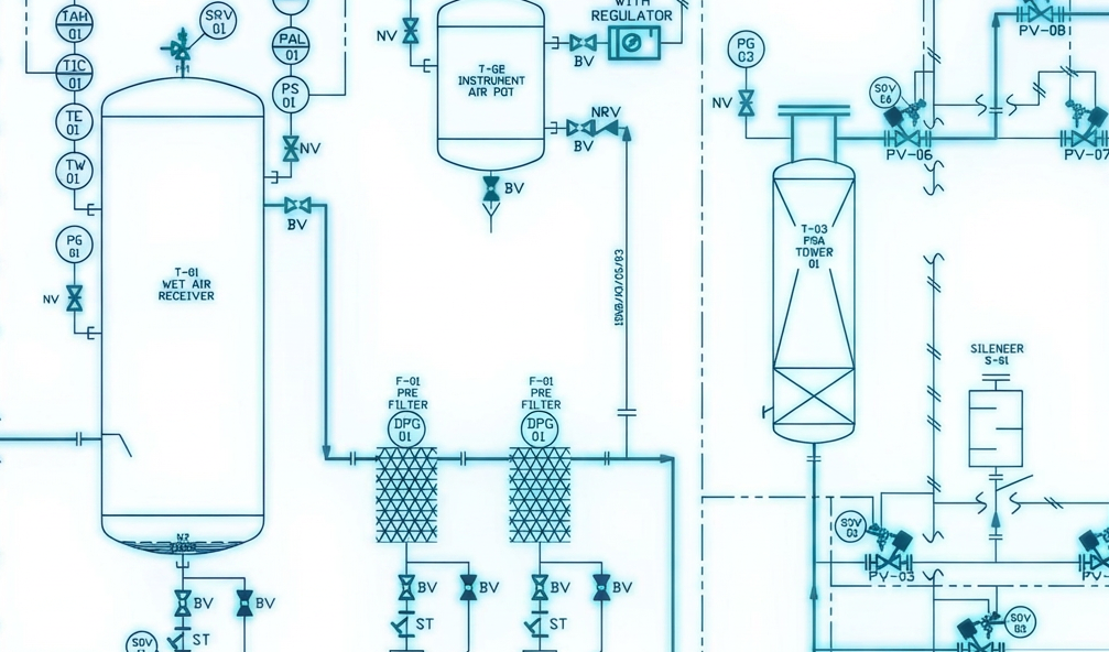
However, handling an alcohol with a flashpoint of 12°C and an explosive range of 6%–36% (% v/v in air) requires a complete rethinking of onboard safety philosophy, where:
- LEL (Lower Explosive Limit) = 6%
- UEL (Upper Explosive Limit) = 36%
requires a complete rethinking of onboard safety philosophy.
Under the IMO IGF Code (adopted by resolution MSC.391(95), made mandatory under SOLAS through the related amendments in resolution MSC.392(95)) and the specific guidelines of MSC.1/Circ.1621, maintaining an inert atmosphere across the entire fuel system and related auxiliary systems is a continuous operational mandate.
The core defence mechanism is the onboard nitrogen (N₂) system.
For marine systems engineers, designing this system means moving beyond generic standard calculations. It demands precise, dynamic assessment and piping sizing calculations across multiple distinct, overlapping operational scenarios: active ullage blanketing, annular space protection (double-walled piping), pipe purging, and vent mast emergency dilution.
It means at concentrations in air below the LEL, there is not enough methanol vapor to spread a flame. At concentrations in air above the UEL, there is too much methanol and not enough oxygen to spread a flame.
Methanol institute Methanol Institute — Safe Handling Manual
Quick Facts
– Nitrogen keeps tank oxygen levels below 8% by volume, often tightened to below 5% under DNV and Lloyd’s Register
– The nitrogen generator must be sized on the maximum volumetric fuel displacement onboard.
– The annular space of double-walled fuel piping is kept under a static nitrogen overpressure.
– Generator trains should be sized with n+1 redundancy wherever the fuel arrangement allows it
Tank Ullage Blanketing: The Continuous Consumption Base Load
The primary application of N₂ on a methanol-fuelled vessel is the continuous inerting of the fuel storage and daily tanks.
We size the system to keep oxygen (O₂) levels below 8% by volume, and often below 5% under the more conservative approach adopted by classification societies such as DNV and Lloyd’s Register.
It’s worth remembering why that margin matters: methanol’s own Limiting Oxygen Concentration (LOC) sits close to 10.7% O₂ by volume, so working to 8%, and tighter still to 5%, isn’t an arbitrary number, it’s a deliberate buffer, in other terms a safety margin against that include instrumentation readings, stratification in the ullage, and the uncertainties that always creep into a real installation.

Where:
V_discharge is the maximum volumetric discharge rate of the methanol fuel pumps m3/h .
C_safety is a safety margin factor (typically 1.15 to 1.20) to account for transient pressure drops.
Q_thermal is the rate of nitrogen makeup required when a sudden ambient temperature drop
Dimensioning Methodology
We’ve seen it many times on drawing review: dimensioning the inert gas generator (typically based on hollow-fibre membrane technology) using calculation assumptions based solely on SFOC or purging volume.
The dimensioning calculation must be governed by the maximum volumetric fuel displacement occurring onboard. Typically, the most severe volumetric change onboard is represented by fuel transfer, driven by the methanol transfer pumps.
So, the peak nitrogen flow rate Q_blanket is calculated using the maximum fuel transfer rate, combined with thermal breathing parameters derived from ISO 28300 / API 2000.
The working philosophy of inert gas in the methanol tank follows this process:
- During bunkering/filling: The rising fuel level forces out the inert gas. The system must direct this methanol vapour through a dedicated vapor return line to shore/bunker vessel, or handle it via high-velocity pressure/vacuum (P/V) valves linked to the vent mast.
- During fuel consumption: The N₂ injection branches and regulating valves maintain a stable, slight positive overpressure — typically in the low hundreds of mbar, sized against the specific tank design pressure and generator/engine manufacturer data, to prevent vacuum formation that would otherwise accelerate methanol vapour generation.
We’d also size the generator train with n+1 redundancy in mind wherever the fuel arrangement allows it: losing blanketing capacity to a filter change or a membrane fault is not something you want to discover during bunkering.
Double-Walled Pipe and Annular space inerting gas
The IGF Code requires that all fuel piping passing through enclosed spaces be double-walled (jacket pipe), with the outer pipe acting as a secondary containment boundary. The annular space must be either continuously ventilated or filled with an inert gas. For most machinery space layouts, an active, pressurized nitrogen-inertized annular space is the preferred engineering solution.
Flow and Pressure Profile
The piping design must handle two distinct operational profiles in the annulus: static monitoring and dynamic flushing.
- Static Monitoring: The annulus is pressurized with N₂ to a benchmark pressure held above the maximum fuel supply pressure, the exact margin is a design figure to confirm against the approved arrangement and class documentation, not a fixed rule. Any drop in annulus pressure indicates an integrity breach in either the outer casing or the inner core pipe, and it should be treated as a hazardous area classification event until proven otherwise, the machinery space around the breach effectively inherits the risk profile of the fuel side until the leak is confirmed and isolated.
- Dynamic Flushing: Following a fuel system shutdown or an Emergency Shutdown (ESD) trip, the entire inner core pipe must be completely purged of liquid methanol and subsequent vapor before maintenance or prolonged stop period.
Purging pipeline and other piping considerations
The volume of nitrogen required for a dynamic purge is calculated based on displacing the total internal volume of the core fuel lines V_core within a class-mandated timeframe, typically less than 10 minutes.
To achieve a clean sweep without leaving localized fluid pockets in low isometric runs, the nitrogen must achieve a turbulent flow regime inside the pipe. The Reynolds number (Re) for the nitrogen gas flush must exceed 4000:
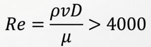
Where:
- ρ is the nitrogen density at purge pressure.
ν is the velocity.
D is the inner diameter of the core pipe.
μ is the dynamic viscosity of nitrogen.
- To prevent over-sizing the primary nitrogen generator for a transient event, the nitrogen piping system must integrate a high-pressure N2 Buffer (pressure vessel)
Pipe branch characteristics and valves required in nitrogen systems:
No Pockets: The N2 supply lines feeding the vent mast injection rings must be completely self-draining. Any condensation trap in the nitrogen line can freeze during rapid depressurization or block gas flow during an emergency trip.
Check Valve Placement: Double block-and-bleed valve arrangements must be located as close to the mast injection interface as possible to prevent methanol vapor from migrating backward into the ship’s main N2 distribution manifold during the non-purging state.
The importance behind the nitrogen system
The nitrogen system plays an extremely important role on methanol-fuelled vessels, as it is responsible for inerting not only the methanol fuel tank but also the annular space of the double-walled pipes and purging methanol pipelines.
Given its critical importance for onboard safety, properly dimensioning the nitrogen generator and the nitrogen piping system is fundamental to avoiding unwanted surprises during commissioning.
Many naval engineering companies are not used to working with nitrogen systems, and as a result, nitrogen generators are often improperly dimensioned or pipelines incorrectly designed.
At Flowazur Consulting, we support shipyards during the piping engineering or feasibility study phase of methanol-fuelled projects. We assess the ship’s profile, the installed power and consumers, and their relative SFOC (Specific Fuel Oil Consumption).
Starting from this point, through to the transfer pumps, we carry out piping calculations to determine the correct nitrogen generator and piping system sizing, reducing overall project risk and rework in later phases of the project.
Book a call with our engineers to discuss your project in detail.
Frequently Asked Questions
Q: Why do methanol-fuelled ships need an onboard nitrogen system?
A: Methanol has a flashpoint of 12°C and an explosive range of 6%–36% in air, so tanks, double-walled piping annuli, and fuel lines must stay continuously inert.
Q: What oxygen level must the nitrogen system maintain in the tanks?
A: Below 8% O2 by volume, tightened to below 5% under the more conservative approach used by class societies such as DNV and Lloyd’s Register.
Q: What should nitrogen generator sizing be based on?
A: The maximum volumetric fuel displacement onboard, typically driven by the methanol transfer pumps — not SFOC or purge volume alone.
Q: Why is the annular space of double-walled piping kept under nitrogen pressure?
A: A pressurized annulus lets any pressure drop signal an integrity breach in the outer casing or inner core pipe before it’s confirmed.
Q: How fast must a dynamic nitrogen purge clear the fuel lines?
A: Within a class-mandated timeframe, typically under 10 minutes, at a Reynolds number above 4000 to avoid leaving liquid pockets.
Q: Why size the nitrogen generator train with n+1 redundancy?
A: So a filter change or membrane fault doesn’t interrupt tank blanketing — especially risky if it happens during bunkering.