
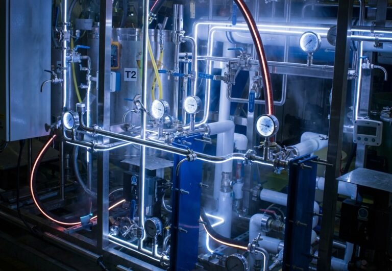
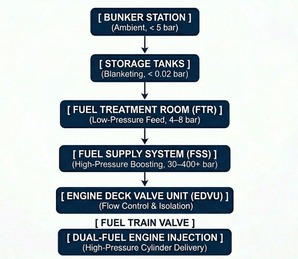
Implementing methanol as a primary marine fuel requires looking beyond isolated components such as storage tanks or fuel supply skids. From the moment methanol crosses the bunker manifold flanged connection to its high-pressure injection into the engine cylinders, the fuel undergoes significant changes in pressure and temperature. Engineering this process demands a strict focus on fluid dynamics and on managing pressure and flow rate under all operational conditions.
Marine systems engineers have to assess the ship layout, define suitable system routing and skid positions, and ultimately design the methanol fuel system around which the tank and auxiliary systems operate and interact.
The methanol fuel system belongs to the broader family of low-flashpoint fuel systems, methanol having a flashpoint of only 12°C. As with conventional fuels, it’s divided into three main parts:
- Bunkering system
- Transfer system
- Fuel supply system
The methanol fuel supply system is responsible for delivering the correct flow rate, pressure and temperature to the consumers, in a safe environment. It draws fuel from the tank, processes it in the fuel treatment room (FTR) to satisfy the conditions the consumers impose, and delivers it accordingly.
Quick Facts
– Methanol’s flashpoint (12°C) and high vapour pressure make suction-side pump cavitation the main risk
– Fuel is filtered to 10-micron cleanliness through a duplex filter, the standard most main engine manufacturers require
– The Fuel Train Valve uses a double block-and-bleed configuration to isolate and safely purge the engine fuel line
– Retrofit projects typically need a high-pressure pump (400–500 bar).
– Hazardous-area electrical equipment must be IECEx-certified per IGF Code and MSC.1/Circ.1621 – ATEX alone isn’t the applicable standard outside the EU
Low-Pressure Pump: From Methanol Tank to Fuel Treatment Room
The lifecycle begins in the storage tanks, where methanol is pumped toward the FTR.
At this low-pressure stage, the primary engineering challenge is preventing pump cavitation. Methanol has a significantly higher vapour pressure than conventional marine gas oil (MGO), meaning it turns to vapour far more easily under low-pressure conditions. When designing the suction piping, engineers need precise calculations for Net Positive Suction Head Available (NPSHa):
NPSHa = H(atm) + H(static) − H(fric) − H(vp)
- H(atm) is the atmospheric or nitrogen pressure inside the tank ullage.
- H(static) is the static head of the liquid above the pump impeller.
- H(fric) is the cumulative friction head loss across pipes, valves, and suction strainers.
- H(vp) is the vapour pressure head of methanol.
Due to H(vp), any excessive friction loss from incorrect pipe routing, short-radius elbows, or undersized suction lines pushing fluid velocity up will drop the fluid pressure below its vapour pressure. That triggers localised boiling and pump cavitation, and degraded impellers follow soon after.
Low-Pressure Pump Positions and Type
Low-pressure pumps can be centrifugal or deep-well hydraulically driven.
On most methanol-as-fuel projects we’ve seen, deep-well hydraulically driven pumps are the preferred choice, though centrifugal pumps perform perfectly well when a positive suction head is available.
The low-pressure pump position depends on which type is selected.
All machinery working with methanol in a hazardous area has to be certified for explosive atmospheres in line with the hazardous area classification set by the IGF Code and MSC.1/Circ.1621; in practice, equipment rated per the IEC 60079 series (Ex-certified, via IECEx or an equivalent scheme). It’s worth being precise here: “ATEX” is an EU directive, not an IMO instrument, so it isn’t the certification the Code itself calls for. A non-EU flagged, non-EU built vessel would still be fully compliant with IECEx-certified equipment alone, and specifying “ATEX” on a project outside Europe can create unnecessary confusion during procurement.
Duplex Filters
Once suctioned from the methanol settling or daily tank, the fuel passes through a duplex filter to reach a cleanliness grade of 10 microns, the standard most main engine manufacturers specify.
Methanol fuel systems carry high-precision components with very tight internal tolerances, making them more sensitive to contamination than conventional HFO or MGO systems.
Engines such as the MAN B&W ME-LGIM and WinGD X-DF-M typically require absolute filtration at 10 microns to keep the fuel injection equipment running reliably.
The duplex configuration allows maintenance without interrupting fuel supply: filter unit A stays in service while unit B sits on standby.
"10-micron double block-and-bleed duplex filter"
Alfa laval - Fuel Conditioning Module Methanol AlfaLaval
Fuel Train Valve
In a methanol-fuelled ship, the Fuel Train Valve (FTV) is one of the most important safety and control components in the fuel supply system. It is not a single valve but a valve arrangement, a valve train, designed to:
- Control methanol flow to the engine.
- Provide emergency shut-off capability.
- Isolate the engine from the fuel system.
- Prevent uncontrolled fuel release.
- Support automatic safety shutdown sequences.
This valve arrangement is connected to the nitrogen system for all maintenance purposes and flushing operations.
Safe operation is ensured by a double-block-and-bleed valve configuration, a well-recognised arrangement that allows the lines to be shut off through two valves in series, with a bleed valve in between to remove any fuel trapped between them.
High-Pressure Pump: Is It Always Required?
The high-pressure pump (HPP) is the component responsible for generating the injection pressure required for atomisation and combustion, pressurising methanol upstream of the main engines to 400–500 bar.
The installation of a high-pressure pump in the fuel supply system is required in retrofit projects, where it operates in place of the main engine’s own high-pressure pump.
This introduces several challenges for the maritime industry, as the fuel must be transported at very high pressure to the main engines. Even a minor leak at this pressure can result in a dangerous vaporised spray.
Furthermore, the high-pressure double-walled piping installed between the fuel treatment room and the consumers has shown stress-related issues once installed onboard, making an in-depth assessment necessary to correctly size supports and select the appropriate pipe type.
New methanol main engines address many of the above challenges by integrating a high-pressure pump directly, making it possible to deliver methanol to the engines at low pressure , typically 10–13 bar.
In practical terms, in the majority of retrofit projects a high-pressure pump will be required, and consequently high-pressure double-walled piping as well. In newbuilding projects, there is a strong likelihood that the high-pressure pump will not be needed, reducing onboard risk and eliminating the need for high-pressure double-walled piping.
Low-Flashpoint Fuel System Complexity
The methanol fuel system, like other alternative fuel systems, can be considered part of modern marine engineering, as many new technologies are adopted and integrated onboard. However, the new design philosophy combined with the new machinery involved makes the design and integration of a methanol fuel system a challenging task.
An engineering team used to working with conventional fuels can put in considerable effort and still overlook critical assessments, such as:
- Minimising the suction height for methanol pumps.
- Missing the correct double-walled pipe installation in one or more areas.
- Failing to properly assess high-pressure double-walled pipe supports and routing to reduce stress.
Missing one or more of these considerations can lead, in the best case, to project revisions and loss of time and, in the worst case, to costly rework onboard.
At Flowazur, we support shipyards and shipowners during the piping engineering phase of methanol-as-fuel implementation, reducing technical uncertainties and project risk while simplifying the overall engineering process.
Book a call with our engineers to discuss your project in detail.
Frequently Asked Questions
Q: What are the three parts of a methanol fuel system?
A: The bunkering system, the transfer system, and the fuel supply system, which delivers fuel at the correct flow rate, pressure and temperature to the engine.
Q: Why is pump cavitation a risk with methanol?
A: Methanol has a much higher vapour pressure than conventional marine gas oil, so it vaporises more easily under low-pressure suction conditions – engineers calculate NPSHa to avoid it.
Q: What cleanliness grade does methanol fuel need?
A: 10 microns, achieved through a duplex filter, which most main engine manufacturers such as MAN B&W and WinGD specify for their methanol engines.
Q: Is ATEX certification enough for methanol equipment outside Europe?
A: No; the IGF Code and MSC.1/Circ.1621 call for IECEx-certified equipment; ATEX is an EU directive, not the IMO-referenced standard.
Q: Does every methanol project need a high-pressure pump?
A: Retrofit projects usually do, since they add an external HPP; newbuild engines with the pump integrated can run on low-pressure fuel supply instead, at 10–13 bar.
Q: What does the Fuel Train Valve do?
A: It’s a valve arrangement, not a single valve, that controls flow to the engine, provides emergency shut-off, isolates the engine, and supports automatic safety shutdown.