
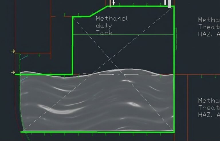
Building methanol storage tanks into a vessel requires a different philosophy in relation to conventional heavy fuel oil (HFO) tank design. Methanol is a low flashpoint, toxic liquid that is fully miscible in water, and its storage is governed by a regulatory framework that’s easy to get wrong on paper: the IGF Code’s Part A-1 only covers natural gas.
Methanol and ethanol sit outside it, and are addressed instead by the IMO Interim Guidelines for the Safety of Ships Using Methyl/Ethyl Alcohol as Fuel (MSC.1/Circ.1621), applied through the Alternative Design route of SOLAS regulation II-1/55.
In practice this means every methanol installation still has to demonstrate an equivalent level of safety to the satisfaction of the flag Administration.
For structural engineers and technical offices, the core challenge is not only containing this new alternative fuel, but isolating it properly. Under the Interim Guidelines, a methanol fuel tank cannot simply share a bulkhead with safe spaces. It requires a cofferdam arrangement that acts as a protective barrier.
We design these structures the way we’d approach any other naval structure exposed to fatigue and accidental damage, and on top of that, they need a chemically resistant, corrosion-resistant coating on every surface that could see methanol.
Quick Facts
– Cofferdams can be avoided only on three boundaries: shell plating below the lowest possible waterline, another methanol tank, or the fuel preparation space.
– Methanol’s lower energy density means a fuel tank needs more than double the volume of an equivalent HFO tank for the same power output.
– Carbon steel tanks need an alcohol-resistant coating – Inorganic Zinc Silicate is recommended over Novolac or Phenolic epoxy systems.
Fuel tank is any integral, independent or portable tank used for storage of fuel. The spaces around the fuel tank are defined as follows:
IMO - IGF Code Guidelines for Methy/Ethyl Alchol as Fuel
- Fuel storage hold space: the space surrounding a fuel containment system, if fitted.
- Cofferdam: a structural space around the fuel tank providing an added layer of gas- and liquid-tight protection against external fire and toxic, flammable vapours.
- Tank connection space: the space surrounding all tank connections and valves, required where those connections sit in enclosed spaces.
IGF Code Cofferdam requirements
The relevant clause, paragraph 5.3.2 of MSC.1/Circ.1621, establishes that integral fuel tanks should be surrounded by protective cofferdams, except on surfaces bound by shell plating below the lowest possible waterline, other methanol/ethanol fuel tanks, or a fuel preparation space.
This single provision creates a number of design consequences that are worth spelling out, because the guideline itself doesn’t spell them out clause by clause.
A cofferdam functions as a physical secondary containment zone that surrounds the tank boundaries. It has to satisfy several design criteria:
- Fire integrity dimension: Where the fuel tank boundary faces a machinery space of category A or another high fire-risk room, paragraph 11.4.3 requires a cofferdam of at least 600 mm, insulated to A-60 class.
- Access: Separately, paragraph 5.11.6 requires horizontal hatches or openings into fuel tanks or cofferdams to have a minimum clear opening of 600 mm x 600 mm, and vertical openings not less than 600 mm x 800 mm, specifically so an injured person can be hoisted out. We’ve seen informal discussions in the superyacht sector about tightening these dimensions on very compact hulls, but we’re not aware of any documented, generally applicable agreement between a yard and a class society to reduce them .
- Shared bulkheads not permitted: A methanol tank cannot share a direct bulkhead with accommodation spaces, category A machinery spaces, or other safe areas, except under the specific exemptions in 5.3.2.
- Systems in the cofferdam: Cofferdams have to be arranged for purging or filling with water, kept under monitoring, and equipped with leak detection per paragraph 15.3.2 , both liquid and vapour detection are required in the space, feeding into the ship’s safety system.
Cofferdam layout
Cofferdams surround the tank almost everywhere, but not in every case and knowing where the exceptions apply, rather than assuming them, is where a HAZID-based risk assessment focus on.
Under 5.3.2, the code exempts three specific boundaries:
- shell plating below the lowest possible waterline,
- other methanol tanks,
- and fuel preparation spaces.
The most common real-world example is the fuel preparation (treatment) room sharing a bulkhead directly with the fuel tank, no cofferdam needed there, because the code treats the preparation space itself as an equivalent barrier, provided it carries its own gas and liquid detection.
The waterline exception is really one rule with two different practical outcomes depending on where it applies. For the tank bottom, which sits below the waterline by definition on an operating vessel, the sea effectively works as the second barrier across the whole surface. For the tank’s side shell, the same exception only holds for the portion that stays below the lowest possible waterline; any part of the shell above that line still needs a cofferdam, because it no longer has the sea acting as a barrier against fire or vapour ingress.
Where a cofferdam is required and the design still needs to squeeze space out of the layout, that’s where the risk assessment must show the mitigation strategy, vapour and liquid detection covering the space, drainage arranged, and (in our experience) additional monitoring such as gas detectors or cameras where the layout makes visual inspection difficult, even though the code itself specifies detection requirements rather than naming particular technologies.
Cofferdam for methanol Fuel tank: The big issue
Installing ventilation, a dedicated drainage arrangement and level alarms in a cofferdam is challenging but generally feasible. What can’t be engineered away is the difference in energy density between methanol and HFO.
- Methanol’s Lower Heating Value sits at roughly 19.8 MJ/kg,
- against HFO’s 40–41.5 MJ/kg, call it a factor of two.
In practical terms, matching the power output of 1m³ of HFO takes more than 2m³ of methanol.
That’s the volume challenge the industry keeps running into: more than double the tank volume is needed for the same chemical energy, and the cofferdam arrangement reduce further into what’s usable.
A few sandwich-structure solutions are now reaching commercialisation to claw some of that volume back SRC’s Methanol Superstorage is one example, using a Sandwich Plate System with a solid elastomer core between two steel plates in place of the conventional twin-shell-plus-600mm-cofferdam arrangement, while still aiming to match the safety intent of MSC.1/Circ.1621.
Coating Chemistry and Corrosion Prevention
Methanol is known to be both a solvent and corrosive, particularly when impurities are present. Working with methanol therefore requires careful attention to chemical corrosion and its solvent properties.
For the inner surfaces of the tank, which are in constant contact with methanol, a specialised alcohol-resistant coating must be applied if the tank is constructed in standard structural carbon steel.
Coating can be omitted for tanks built in stainless steel 316L.
But what type of coating is appropriate for a methanol fuel tank in carbon steel?
The maritime sector has considerable experience transporting methanol at sea. The substance is also widely used in the offshore oil and gas industry, injected into flowlines to prevent the formation of methane hydrates (ice-like solids) that can obstruct pipelines.
However, recent retrofit projects where methanol fuel tanks were coated with the same systems used for methanol cargo tanks have shown accelerated degradation. The coatings typically used for methanol cargo tanks are:
- Novolac epoxy
- Phenolic epoxy
In practical terms, these coatings when applied in a fuel tank context do not appear to be the optimal solution.
Leading organisations such as the Maersk Mc-Kinney Møller Center recommend the use of Inorganic Zinc Silicate instead. This solution is not an epoxy-based coating and therefore does not suffer from swelling or other degradation issues associated with epoxy systems.
Piping, nozzles and other tank connection
In the preliminary phase of a project, whether newbuilding or retrofit , it is important not only to execute the scantling calculations, but also to define pipe sizing and routing at an early stage, in order to avoid undesired in-depth reviews later in the project.
Furthermore, for the cofferdam, air flow rate calculations, duct routing, inlet and outlet positions, bilge system design, and level monitoring are all required.
At the top of the tank, pressure transmitters and temperature transmitters with redundancy are installed.
It is clear that the methanol fuel tank follows a considerably different design philosophy compared to conventional fuel tanks, as cofferdams must be integrated and all associated systems positioned within them.
At Flowazur Consulting with our piping engineering service, we assist shipyards and engineering firms during the early phases of the project to optimise engineering costs while simplifying the engineering process, supported by experienced marine systems engineers with strong practical onboard experience.
Book a call with our engineers to discuss your project in detail.
Frequently Asked Questions
Q: Does the IGF Code cover methanol fuel tanks?
A: No. IGF Code Part A-1 only covers natural gas – methanol and ethanol are regulated separately under MSC.1/Circ.1621, applied through the Alternative Design route of SOLAS II-1/55.
Q: When can a methanol fuel tank boundary avoid the cofferdam?
A: On three exempted boundaries only: shell plating below the lowest possible waterline, another methanol/ethanol fuel tank, or the fuel preparation space.
Q: How much bigger does a methanol tank need to be compared to an HFO tank?
A: More than double the volume, since methanol’s Lower Heating Value (~19.8 MJ/kg) is roughly half that of HFO (40–41.5 MJ/kg).
Q: What coating is recommended inside a carbon steel methanol fuel tank?
A: Inorganic Zinc Silicate, since Novolac and Phenolic epoxy coatings have shown accelerated degradation in recent fuel tank retrofits. Stainless steel 316L tanks can skip coating altogether.
Q: What access opening size does a fuel tank or cofferdam need?
A: A minimum clear opening of 600 x 600 mm for horizontal hatches, and 600 x 800 mm for vertical ones, sized so an injured person can be hoisted out (para 5.11.6).