
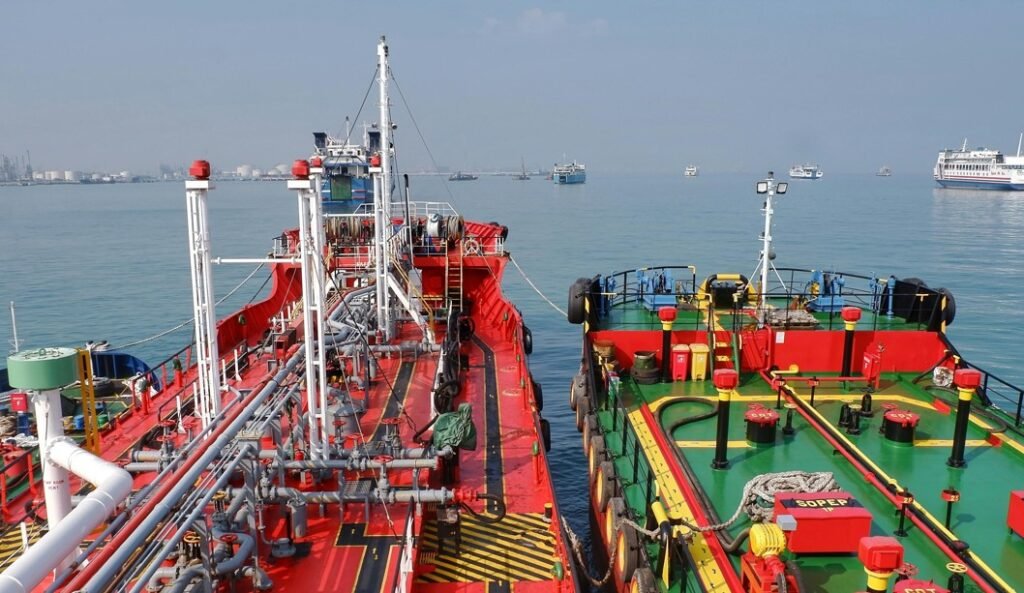
In the alternative fuel landscape, the methanol bunker station is surely one of the most critical operational areas on deck. While fuel treatment rooms handle methanol in a highly monitored environment and without human operation, the bunker manifold is where human operators, third-party shore terminals, or bunker barges physically interface with the vessel, consistently increasing the operative hazard of the system.
Designing this space requires shifting away from conventional heavy fuel oil (HFO, VLSFO, and MGO) layout philosophy.
The governing framework here is the IMO’s Interim Guidelines for the Safety of Ships Using Methyl/Ethyl Alcohol as Fuel (MSC.1/Circ.1621), which mirrors the structure of the IGF Code’s bunkering chapter and is applied together with the methanol-specific rules that classification societies have built on top of it; ABS’s Guide for Methanol and Ethanol Fueled Vessels among them.
Working through this framework, a compliant, shipyard-ready bunker station layout comes down to solving three core technical challenges:
- toxic liquid spill containment,
- closed-loop vapor management,
- and uncompromising physical isolation from the vessel’s safe zones
Quick Facts
– The containment coaming under the manifold must be built in stainless steel (e.g. 316L) or a methanol-resistant epoxy coating.
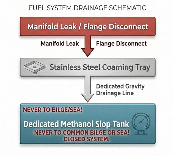
– The coaming drain must run via an independent gravity pipeline (typically DN25 or DN32) straight to a dedicated Methanol Drain Tank.
– A closed-loop Vapor Return Line (VRL), running parallel to the bunkering line with its own manifold connection, is mandatory to keep tank pressure balanced and stop atmospheric venting.
– The area within a 3-metre radius of the bunker manifold is typically classified Zone 1 hazardous.
Spill Containment and Toxic Liquid Management
Unlike LNG or ammonia, which flash into a gas upon release, methanol remains liquid at atmospheric pressure. However, methanol is well known for its low flashpoint of only 12°C.
This means that above 12°C, methanol vapour can build up to a concentration in air that’s within the flammable range, ready to ignite given a source.
Temperatures at this level and above are very common in worldwide shipping, so spills become immediately hazardous, especially in enclosed spaces.
The methanol bunker station can be of closed or semi-closed type. In this space, the Interim Guidelines and the class rules built on them impose strict mitigation measures and systems for spill containment.
Coaming Design and Volume Calculations
The bunkering manifold must be fitted with a dedicated containment coaming, in line with the requirements laid out in MSC.1/Circ.1621
and reflected in ABS’s Guide for Methanol and Ethanol Fueled Vessels.
Volumetric Capacity: The tray must be designed to capture the maximum potential spill volume. The design assumption, and therefore the volume calculation, must take into consideration an ESD (Emergency Shutdown) event, the closure time of the valves, and the average flow rate at which the bunkering operation takes place.
Material Specifications: Methanol is a polar organic solvent, meaning it can degrade standard paints and coatings and cause accelerated corrosion when contaminants are present. Therefore, standard carbon steel coamings are inadequate. The containment tray must be built in stainless steel (e.g., 316L) or treated with specialized, methanol-resistant epoxy coatings.
Drainage Isolation: One of the most common design mistakes on conventionally fuelled vessels is routing the bunker station drain line to the nearest bilge well in the engine room.
The draining system must be fully isolated from all other ship areas.
The containment tray must drain via an independent gravity pipeline (typically DN25 or DN32) directly into a designated Methanol Drain Tank or overflow holding tank, generally located at engine room deck level or in the double bottom.
Vapor production and Vapor Return System
As previously mentioned, methanol is a low flashpoint fuel, and above 12°C its vapour can reach a flammable concentration in air. Another physical characteristic of methanol is its high vapour pressure compared to traditional fuels.
The result of this characteristic is continuous vapour production during bunkering operations. In practical terms, when methanol is transferred into its storage tank, it produces toxic, flammable vapours that have to go somewhere.
In order to maintain pressure under control, preserve tank pressure balance, and prevent atmospheric venting, a closed-loop Vapor Return Line (VRL) interface is mandatory.
Pipe Routing and technology to adopt
The VRL must run parallel to the bunkering line, complete with its own dedicated manifold connection, vapor-tight isolation valves, and nitrogen purging connections.
Pressure Management: The vapour return pipeline requires proper piping engineering calculations to correctly size the line, as it must be able to evacuate the vapour produced under different bunkering conditions.
Therefore, a thorough assessment is required before specifying a pipe diameter.
If the line diameter is too small, backpressure will build within the ship’s storage tanks, triggering automated pressure relief valve trips and interrupting the bunkering operation.
Venting system should be designed with redundancy for the relief of full flow overpressure and/or vacuum. Pressure sensors fitted in each fuel tank, and connected to an alarm system, may be accepted in lieu of the secondary redundancy requirement for pressure relief. The opening pressure of the PRVs should not be lower than 0.007 MPa"
ABS - GUIDE FOR METHANOL AND ETHANOL FUELED VESSELS
As set out in ABS’s Guide for Methanol and Ethanol Fueled Vessels, consistent with the hazardous area approach in MSC.1/Circ.1621, the area within a 3-metre radius of the bunker manifold connections is typically classified as a Zone 1 hazardous area. Any electrical equipment within this envelope; ighting, tank level repeaters, pressure transmitters must be certified for Zone 1 service using an approved protection concept such as Ex ia, Ex ib, Ex d, Ex e, or equivalent.
As with any distance-based requirement pulled from a class guide, it’s worth double-checking against the current edition before it’s locked into the GA, since these figures do get revisited as more methanol projects go through plan approval.
Methanol bunker station closed, semi-closed or open-deck
The general preference under the Interim Guidelines is for the bunkering manifold to sit on an open deck, where natural ventilation helps prevent vapour accumulation.
However, this isn’t always achievable, and in many cases bunker stations end up in closed or semi-closed spaces.
If the methanol bunker station is of this type, additional mitigation systems may be required by the classification society depending on the specific case. In many cases these include:
- Infrared cameras,
- Vapour detectors,
- Dedicated ventilation systems
Furthermore, the structural boundaries separating the bunker station from adjacent internal spaces must integrate:
A-60 Insulation.
For Bulkheads and decks separating the manifold area from machinery spaces, accommodation corridors, or control stations must be insulated to A-60 standard.
Air Intake Prohibitions.
Class guidance typically excludes ventilation air intakes, air conditioning inlets, and accommodation access doors from a zone around the methanol bunker manifold, commonly in the order of 9 metres, though this should be confirmed against the specific class rule in force for the project.
Enforcing this on a compact vessel demands extensive coordination between the structural, HVAC, and piping design teams to make sure exhaust streams from other machinery zones don’t end up cross-contaminating the bunker area.
Many differences and additional complexity
Compared to a conventional bunker station, it is clear that methanol bunker stations are more complex and more sensitive to hazard. For an engineering or technical team accustomed to working with conventional fuels, designing and dimensioning this new type of bunker station can be challenging, and one or more details can escape the less experienced technician.
At Flowazur, our marine systems engineers have direct experience with methanol fuel systems. We offer piping engineering support to EPCs, shipyards, and OEMs to reduce project risk and improve engineering phase efficiency.
Book a call with one of our engineers to discuss your project.
Frequently Asked Questions
Q: What material should a methanol containment coaming be made of?
A: Stainless steel (e.g. 316L) or a specialized methanol-resistant epoxy coating; standard carbon steel is inadequate because methanol degrades conventional paints and accelerates corrosion.
Q: Where should the coaming drain line go?
A: Via an independent gravity pipeline (typically DN25 or DN32) straight to a dedicated Methanol Drain Tank.
Q: What is a Vapor Return Line (VRL) and why is it mandatory?
A: A closed-loop pipeline that runs parallel to the bunkering line, with its own manifold connection, to keep tank pressure balanced and prevent atmospheric venting of toxic, flammable vapour during transfer.
Q: How far does the Zone 1 hazardous area extend around the bunker manifold?
A: Typically a 3-metre radius, within which electrical equipment must carry Ex ia, Ex ib, Ex d, Ex e, or equivalent certification for Zone 1 service.
Q: Can a methanol bunker station be enclosed instead of on open deck?
A: The Interim Guidelines generally prefer an open-deck manifold for natural ventilation, but closed or semi-closed stations are common and require added mitigation measures: infrared cameras, vapour detectors, dedicated ventilation, and A-60 insulated boundaries.